Wiki mirrorView source
The information in this page is updated in accordance with firmware version RUT2M_R_00.07.22.1.
Summary
The Network page contains information related to the device's networking. This chapter is an overview of the Network page in RUT200 devices.
Mobile
The Mobile tab displays information about the mobile connection. The figure below is an example of the Mobile tab:
Note: If the device supports dual SIM functionality, it has an additional feature called "Switch to next SIM slot". See the table below:
| Action buttons | Description |
|---|---|
| Switch to next SIM slot | After proceeding, you will lose current mobile connection. A temporary connection will be established with the next SIM slot. After rebooting the device, the default SIM will be used for the connection. |
| Restart connection | Initiates Mobile connection restart. |
| Field name | Description |
|---|---|
| SIM card state | The current SIM card state. Possible values are:
|
| Provider | Network operator's name |
| IMSI | The IMSI (international mobile subscriber identity) is a unique 15 decimal digit (or less) number used to identify the user of a cellular network |
| ICCID | SIM card's ICCID - a unique serial number used to identify the SIM chip |
| Operator | Network operator's name |
| Operator state | Shows whether the network has currently indicated the registration of the mobile device. Possible values are:
|
| Data connection state | Indicates whether the device has a mobile data connection or not. |
| Connection stage | Show intermediate stages of mobile connection establishing process. |
| Network type | Mobile network type. Possible values are:
|
| IP address | Mobile interface IP address |
| Uptime | Mobile connection Uptime |
| Carrier Aggregation | LTE Advanced Carrier Aggregation, CA, is one of the key techniques used to enable the very high data rates of 4G to be achieved. By combining more than one carrier together, either in the same or different bands it is possible to increase the bandwidth available and in this way increase the capacity of the link. |
| Bandwidth | Bandwidth describes the maximum data transfer rate of Internet connection. |
| Connected band | Currently used mobile frequency band. |
| Signal quality | Calculated indicator of overall cellular connection quality. The calculations performed based on network type:
|
| APN | Access Point Name. |
| MTU | Maximum Transmission Unit. |
| Data received | Amount of data received through the mobile interface |
| Data sent | Amount of data sent through the mobile interface |
| Cell ID | The ID of the cell that the modem is currently connected to |
| LAC/TAC |
|
| Physical cell ID | Physical Cell ID is an identification of a cell at physical layer. |
| ARFCN | In mobile cellular networks, an absolute radio-frequency channel number (ARFCN) is a code that specifies a pair of physical radio carriers used for transmission and reception in a land mobile radio system, one for the uplink signal and one for the downlink signal. |
| Mobile country code | The Mobile Country Code, abbreviated as MCC, is the code uniquely identifying the home country of a (Glossary:Mobile network operator (MNO|mobile network operator (MNO). |
| Mobile network code | Mobile Network Code (MNC) is a unique two- or three-digit number used to identify a home Public Land Mobile Network (PLMN) to. MNC is allocated by the national regulator. |
If mobile data limit is set and reached, near Connection column warning mark will appear. E.g.:
| Bands information | Connected band |
|---|---|
| Other signal level measurements | Overall signal quality for different network types is defined by different measurements. Short explanations and recommendations are provided below. Click here for more in-depth information or click on one of the links below:
|
LAN
This tab displays information about the device's local network(s). The figure below is an example of the Network window:
| Field name | Description | DHCP Leases |
|---|---|---|
| Address | IP address of the LAN interface | |
| Netmask | Netmask of the LAN interface. In a sense, a netmask specifies the size of a network. In other words, it indicates which part of the IP address denotes the network, and which denotes the device | |
| Interface | Interface which leased the address | |
| Hostname | Hostname of a LAN client | |
| IP Address | IP address of a LAN client | |
| MAC Address | MAC address of a LAN client | |
| Leasetime Remaining | Remaining lease time for a DHCP client. Active DHCP lease holders will try to renew their DHCP leases after a half of the lease time passes. | |
| Static Lease | This action will reserve currently assigned IP address for the device in Network -> Interfaces -> Static leases. |
Similarly there is an IPv6 dedicated tab.
| Field name | Description | DHCP Leases |
|---|---|---|
| Address | IP address of the LAN interface | |
| Delegated prefix | The delegated prefix is a smaller subnet given to a device to lease IPv6 addresses for its own DHCPv6 clients. | |
| Interface | Interface which leased the address | |
| Hostname | Hostname of a LAN client | |
| Address | IP address of a LAN client | |
| Delegated prefix | The delegated prefix is a smaller subnet given to a device to lease IPv6 addresses for its own DHCPv6 clients. | |
| DUID | DHCP unique identifier is used by DHCPv6 to identify device. Similar to MAC that is used by DHCPv4. | |
| Leasetime Remaining | Remaining lease time for a DHCP client. Active DHCP lease holders will try to renew their DHCP leases after a half of the lease time passes. | |
| Static Lease | This action will reserve currently assigned IP address for the device in Network -> Interfaces -> Static leases. |
Firewall
This page displays information about the device's firewall. Info is shown of IPv4 and IPv6 traffic. The figure below is an example of the Chains and Rules sections:
| Field name | Description |
|---|---|
| Reset counters | Resets all traffic and packet fields |
| Name | Name of the chain |
| Traffic | Size of traffic that was matched to the chain |
| Packets | Count of packets that were matched to the chain |
| Policy | Policy for traffic entering the zone. |
| Rules | Count of rules the chain has |
| References | Count of times the chain was referenced in other chains |
For more information about specific firewall chain, View button can be pressed. Window like this should pop up:
| Field name | Description |
|---|---|
| Traffic | Size of traffic that was matched to the rule |
| Packets | Count of packets that were matched to the rule |
| Target | Name of the rule (if highlighted you can click it to open modal to it) |
| Protocol | Filters by Internet protocol |
| In | Filters by inbound interface |
| Out | Filters by outbound interface |
| Source | Filters by source address |
| Destination | Filters by destination address |
| Options | Additional iptables options |
| Comment | Filters by comment |
Rules section - displays rules assigned to chains:
To inspect rules, open chain and press on target. You will be redirected to inner chain modal:
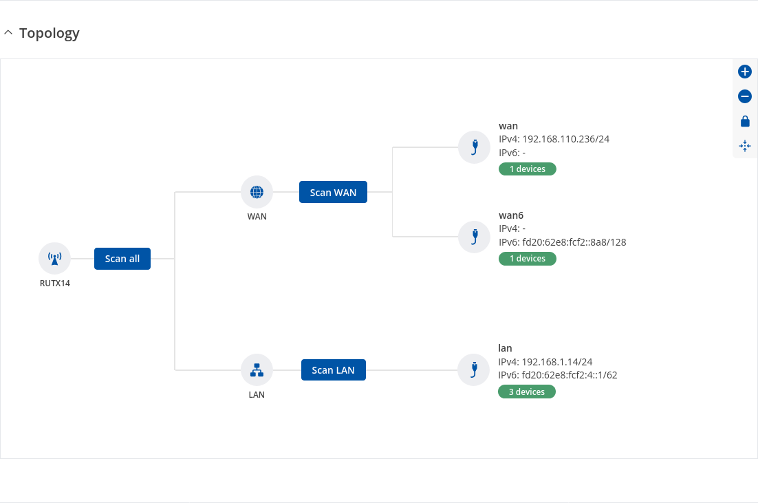
Topology
The Topology tab allows scanning of WAN, LAN or both interfaces via arp scan to check active connected devices. After scan it shows how many active devices were found and on which interface.
Topology scan results
This section displays the results of the scan.
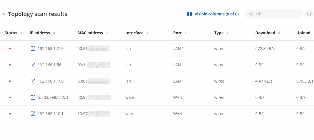
| Field name | Description |
|---|---|
| Satus | Satus of scanned device (green color indicates that device is Up/ red - Down) |
| IP Address | IP address of scanned device |
| MAC Address | MAC address of scanned device |
| Interface | The interface through which the device is connected |
| Port | The physical port through which the device is connected |
| Type | Device connection type |
| Download | Download speed between connected device |
| Upload | Upload speed between connected device |