Wiki mirrorView source
The information in this page is updated in accordance with firmware version RUTX_R_00.07.22.1.
Summary
The Global Positioning System (GPS) is a space-based radionavigation system. This page is an overview of the GPS service in RUTX11 devices.
General
The General is used to enable the GPS service and the support for different types satellites. Once you turn on GPS, you can check the Map page in order to see if the device has obtained a GPS fix. It is very important to attach the GPS antenna on the device and place it outside (not inside of a building). The device will not be likely to obtain a GPS fix otherwise.
The figure below is an example of the General page and the table below provides information on the fields contained in that page:
| Field | Value | Description |
|---|---|---|
| Enabled | off | on; default: off | Turns the GPS service on or off. |
| DPO enabled | off | on; default: off | Enable dynamic power optimization (requires modem reboot). This function is not supported on devices with Meig modems or Quectel BG95 modem |
| Galileo NMEA support* | off | on; default: off | Turns support for Galileo satellites on or off. |
| Glonass NMEA support* | off | on; default: off | Turns support for Glonass satellites on or off. |
| BeiDou NMEA support* | off | on; default: off | Turns support for BeiDou satellites on or off. |
*Changing these options requires a modem reboot. Therefore, if you make changes to these options and save them, the device will lose cellular connectivity for about 30 seconds.
Map
The Map page displays the device's current coordinates and position on the map. To see the device's location on the map, make sure to attach the GPS antenna on the device and enable GPS in the General page.
The figure below is an example of the Map page:
NMEA
The NMEA page is used to configure settings related to NMEA sentence collecting and forwarding.
NMEA forwarding
The NMEA forwarding section is used to configure and enable NMEA forwarding. The figure below is an example of the NMEA forwarding section and the table below provides information on the fields contained in that section:
| Field | Value | Description |
|---|---|---|
| Enabled | off | on; default: off | Turns NMEA forwarding on or off. |
| Host information | ip | host; default: none | Host information, multiple hosts are allowed. Note: If a multicast IP (example: "224.0.0.0") address is added and protocol UDP is selected, a new Interface option appears. |
| Protocol | TCP | UDP; default: TCP | Protocol that will be used to send NMEA data. |
| Port | integer [0..65535]; default: 8500 | Port number off the server to which NMEA data will be forwarded. |
| Interface | interface; default: lan | The option appears when multicast IP is entered and UDP protocol is selected |
| Contain connection | off | on; default: off | Contains active session with the remote server if turned on. |
| Select prefix | none | serial | mac | imei | + Add new; default: none | Prefix is added to the NMEA sentence before it is transmitted.
|
Hosts status
This section displays hosts status information.
NMEA forwarding cache
The device caches NMEA forwarding information if NMEA forwarding is enabled. This section is used to select the memory type where the cache will be stored and the maximum amount of data that will be saved:
| Field | Value | Description |
|---|---|---|
| Save cache in | RAM Memory | FLASH Memory; default: RAM Memory | Selects which type of memory will be used for storing NMEA forwarding cache. |
| Maximum sentences | integer; default: 5000 | Maximum amount of NMEA sentences that will be saved in the cache before older entries are deleted and replaced by new ones. |
| File | filepath; default: none | Location of the file where NMEA forwarding cache information will be stored. This field becomes visible only when the selected memory type is "flash". |
NMEA serial forwarding
This section is used to configure NMEA serial forwarding settings:
| Field | Value | Description |
|---|---|---|
| Enabled | off | on; default: off | Turns NMEA serial forwarding on or off. |
| Select prefix | none | serial | mac | imei | + Add new; default: none | Prefix is added to the NMEA sentence before it is transmitted.
|
NMEA serial ports
This section displays NMEA serial forwarding port instances currently existing on the router. To add a new serial port instance, press 'Add' button:
You will then be taken to the NMEA serial port configuration page:
| Field | Value | Description |
|---|---|---|
| Enable | off | on; default: off | Enable service. |
| Name | string; default: none | Name of serial port. |
| Device | USB RS232 interface; default: USB RS232 interface | Specifies which serial port will be used for serial communication. |
| Baud rate (USB) | integer [300..4000000]; default:9600 | Data rate for serial data transmission (in bits per second (bps)). |
| Data bits | 8; default: 8 | Number of data bits for each character. |
| Stop bits | 1 | 2; default: 1 | Stop bits sent at the end of every character allow the receiving signal hardware to detect the end of a character and to resynchronise with the character stream. Electronic devices usually use one stop bit. Two stop bits are required if slow electromechanical devices are used. |
| Parity | None | Odd | Even | Mark | Space; default: None | In serial transmission, parity is a method of detecting errors. An extra data bit is sent with each data character, arranged so that the number of 1 bits in each character, including the parity bit, is always odd or always even. If a byte is received with the wrong number of 1s, then it must have been corrupted. However, an even number of errors can pass the parity check.
|
| Flow control | None; default: None | In many circumstances a transmitter might be able to send data faster than the receiver is able to process it. To cope with this, serial lines often incorporate a "handshaking" method, usually distinguished between hardware and software handshaking. |
NMEA collecting
The NMEA collecting section is used to enable NMEA sentence gathering and storing. The figure below is an example of the NMEA collecting section and the table below provides information on the fields contained in that section:
| Field | Value | Description |
|---|---|---|
| Enabled | off | on; default: off | Turns NMEA sentence collecting on or off. |
| File | filepath; default: none | Location of the file where NMEA sentences will be stored. This field becomes visible only when NMEA collecting is enabled. |
NMEA sentence settings
The NMEA sentence settings section provides the possibility to configure which NMEA sentences will be forwarded or collected and at what frequency. The figure below is an example of the NMEA sentence settings section and the table below provides information on the fields contained in that section:
| Field | Value | Description |
|---|---|---|
| Forwarding enabled | off | on; default: off | Enables forwarding for the adjacent NMEA sentence. |
| Forwarding interval | positive integer; default: 5 | NMEA sentence forwarding frequency in seconds. |
| Collecting enabled | off | on; default: off | Enables collecting for the adjacent NMEA sentence. |
| Collecting interval | positive integer; default: 5 | NMEA sentence collecting frequency in seconds. |
Note: Not all types of NMEA sentences in the module are compatible with all modems. More information about supported NMEA sentences can be found on the modem module manufacturer's page.
NMEA sentence reference table:
| NMEA sentence name | Description |
|---|---|
| GPGSV | Number of GPS satellites in view. |
| GPGGA | GPS fix data. |
| GPVTG | GPS track made good and speed relative to the ground. |
| GPRMC | Recommended minimum specific GPS/Transit data. |
| GPGSA | GPS DOP and active satellites. |
| GLGSV | Number of GLONASS satellites in view. |
| GNGSA | GNNS DOP and active satellites. |
| GNGNS | GNSS position fix from more than one constellation (e.g., GPS + GLONASS). |
| GAGSV | Number of Galileo satellites in view. |
| PQGSV | Number of BeiDou satellites in view. |
| PQGSA | BeiDou DOP and active satellites. |
| GARMC | Recomended minimum specific for Galileo data. |
| GAGGA | Galileo fix data. |
| GAGSA | Galileo DOP and active satellites. |
| GAVTG | Galileo track made good and speed information relative to the ground. |
| GLGSA | GLONASS DOP and active satellites. |
| GLGNS | GLONASS position fix from more than one constellation. |
| GNGSV | Multi-constellation - GNSS satellites in view, such as number of satellites in view and satellite ID number |
| PQGGA | BeiDou fix data. |
| PQRMC | Recommended minimum specific GNSS data. |
| PQVTGC | BeiDou course over ground and ground speed. |
| GNGGA | Multi-constellation - GPS fix data. |
| GNRMC | Multi-constellation - recommended minimum specific GNSS data. |
| GNVTG | Multi-constellation - course over ground and ground speed. |
| GBGSV | Detailed satellite data (used in BeiDou sentences). |
| GBGSA | BeiDou DOP and active satellites. |
| GQGSV | Detailed QZSS satellite data (QZSS regional GPS augmentation system (Japan)). |
| GQGSA | QZSS DOP and active satellites (QZSS regional GPS augmentation system (Japan)). |
| GPGLL | Geographic position, latitude, longitude. |
| PQGLL | |
| GBGGA | BeiDou - GPS fix data. |
| GBRMC | BeiDou - recommended minimum specific GNSS data. |
| GBVTG | BeiDou - course over ground and ground speed. |
| GBGLL | BeiDou - longitude and latitude. |
| GPGNS | GPS position fix from more than one constellation. |
| GAGNS | Galileo position fix from more than one constellation. |
| BDGGA | BeiDou fix data. |
| BDRMC | BeiDou fix data. |
| BDGSV | BeiDou - Number of BeiDou satellites in view. |
| BDGSA | BeiDou DOP and active satellites. |
| BDVTG | BeiDou course over ground and ground speed. |
| BDGNS | BeiDou position fix from more than one constellation. |
HTTPS
The HTTPS page can be used to configure data sending to an HTTP(S) server.
HTTPS/HTTP server settings
The HTTPS/HTTP Server Settings section is used to enable GPS data sending to an HTTP or HTTPS server.
| Field | Value | Description |
|---|---|---|
| Enabled | off | on; default: off | Turns data sending to HTTP/HTTPS server on or off. |
| URL | url string; default: none | URL of the remote server (ex. example.com/xxxx). |
| Interval | integer; default: none | Interval on which collected NMEA sentences should be forwarded. |
Servers status
This section displays remote servers status information.
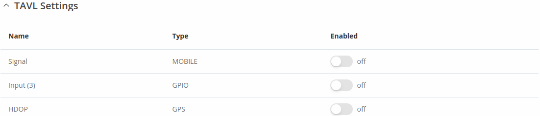
TAVL settings
The TAVL settings section is used to select which data will be sent to the TAVL server:
| Field | Value | Description |
|---|---|---|
| Signal | off | on; default: off | Includes GSM signal strength information in the GPS data sent to server. |
| Input (3) | off | on; default: off | Includes din1 status information in the GPS data sent to server. |
| HDOP | off | on; default: off | Includes horizontal dilution of precision in the GPS data sent to server. |
Note: TAVL signal rule indicates signal strength (RSSI) and returns numerical value according to this table:
| No. of Value | Signal strength |
|---|---|
| 0 | No signal |
| 1 | <= -97 dBm |
| 2 | -82 dBm to -97 dBm |
| 3 | -67 dBm to -82 dBm |
| 4 | -52 dBm to -67 dBm |
| 5 | >= -52 dBm |
AVL
The AVL page is used to set up GPS data sending to an AVL server.
General status
This section displays AVL general status information.
Hosts status
This section displays hosts status information.
AVL server settings
The AVL server settings section is used to configure the main parameters of data sending to an AVL server. The figure below is an example of the AVL Server Settings section and the table below provides information on the fields contained in that section:
| Field | Value | Description |
|---|---|---|
| Enabled | off | on; default: off | Turns data sending to AVL server on or off. |
| Retry on Fail | off | on; default: off | Turn retries in case of a failed attempts on or off. When turned on, the device will try to send the same data to the server until the transmission is successful. |
| Hostname | ip | host; default: 192.168.0.1 | IP address or hostname of an AVL server. |
| Protocol | TCP | UDP; Default: TCP | Protocol that will be used for communication with the AVL server. |
| Port | integer [0..65535]; default: 8501 | TCP/UDP port number of the AVL server to which the device will be connecting. |
| Don't Contain Connection | off | on; default: off | When turned on, handles each AVL packet iteration as a new connection. When turned off, connects once and uses the same socket for future communication. |
| Static Navigation | off | on; default: off | Stop collecting NMEA data if object is stationary. Ignores data when speed equals to 0 or same as previous coordinates (rounded to 4 decimals). |
Main rule
The Main rule section defines how and when GPS data will be collected and sent to a specified AVL server. Refer to the figure and table below for information on the configuration fields of Main Rule.
| Field | Value | Description |
|---|---|---|
| Enable | off | on; default: on | Turns the main rule on or off. |
| Rule priority | Low priority level | High priority level | Panic priority level | Security priority level; default: Low priority level | The rule's priority. Different priority settings add different flags to event packets, so they can be displayed differently in the receiving system. The device sends data of higher priority first. Priority levels from highest to lowest are as follows:
|
| Collect period | integer [1..999999]; default: 5 | How often (in seconds) data will be collected. |
| Min distance | integer [1..999999]; default: 50 | Minimum distance change (in meters) before sending records. |
| Min angle | integer [1..360]; default: 50 | Minimum angle change (in degrees) before sending records. |
| Min accuracy | integer [1..999999]; default: 10 | Minimum accuracy (in meters) required before saving record. The lower the accuracy value, the better. |
| Min saved records | integer [1..32]; default: 20 | Minimum amount of gathered records before sending. |
| Send period | integer [0..999999]; default: 60 | How often (in seconds) gathered data is sent. |
Secondary rules
The Secondary rules section provides you with the possibility to create additional data sending rules. The difference from the main rule is that the secondary rules only send data when the device uses a specified type of WAN and when the digital isolated output is in the specified state.
Refer to the figure and table below for information on the configuration fields of the Secondary rules section.
| Field | Value | Description |
|---|---|---|
| Enable | off | on; default: off | Turns the secondary rule on or off. |
| WAN | Mobile Both | Mobile Home | Mobile Roaming | Wired; default: Mobile Home | Selects which type of WAN will trigger the rule. |
| Ignore | off | on; default: off | If enabled, the rule ignores state of input. |
| IO level | Low level | High level | Both; default: High level | Selects which input state will trigger the rule. |
| IO type | GPIO; default: GPIO | Selects input type. |
| IO name | Input (4); default: Input (3) | Selects which specific input will trigger the rule. |
| Rule priority | Low priority level | High priority level | Panic priority level | Security priority level; default: High priority level | The rule's priority. Different priority settings add different flags to event packets, so they can be displayed differently in the receiving system. The device sends data of higher priority first. Priority levels from highest to lowest are as follows:
|
| Collect period | integer [1..999999]; default: 10 | How often (in seconds) data will be collected. |
| Min distance | integer [1..999999]; default: 25 | Minimum distance change (in meters) before sending records. |
| Min angle | integer [1..360]; default: 25 | Minimum angle change (in degrees) before sending records. |
| Min accuracy | integer [1..999999]; default: 10 | Minimum accuracy (in meters) required before saving record. The lower the accuracy value, the better. |
| Min saved records | integer [1..32]; default: 10 | Minimum amount of gathered records before sending. |
| Send period | integer [0..999999]; default: 10 | How often (in seconds) gathered data is sent. |
TAVL settings
The TAVL settings section is used to select which data will be sent to the TAVL server:
| Field | Value | Description |
|---|---|---|
| Signal | off | on; default: off | Includes GSM signal strength information in the GPS data sent to server. |
| Din1 | off | on; default: off | Includes Din1 status information in the GPS data sent to server. |
Note: TAVL signal rule indicates signal strength (RSSI) and returns numerical value according to this table:
| No. of Value | Signal strength |
|---|---|
| 0 | No signal |
| 1 | <= -97 dBm |
| 2 | -82 dBm to -97 dBm |
| 3 | -67 dBm to -82 dBm |
| 4 | -52 dBm to -67 dBm |
| 5 | >= -52 dBm |
AVL I/O
The AVL I/O tab provides you with the possibility to configure input rules.
Input Rules
The Input Rules section displays existing input rules. To create a new input rule click the 'Add' button.
After this you should be redirected to configuration page of the newly added rule, which should look similar to this:
| Field | Value | Description |
|---|---|---|
| Enable | off | on; default: on | Turns the input rule on or off. |
| Input type | Input (3); default: Input (3) | Select type on your own intended configuration. |
| Trigger | Input active | Input low | Both; default: Input active | Select trigger event for your own intended configuration. |
| Priority | Low | High | Panic | Security; default: Low | The rule's priority. Different priority settings add different flags to event packets, so they can be displayed differently in the receiving system. The device sends data of higher priority first. |
GPS Geofencing
A geofence is a virtually defined boundary for a real-world geographic area. The GPS Geofencing page provides you with the possibility to set this custom area and apply rules that will inform you when the device leaves or enters the geofence.
To create a new geofence area, enter a custom name for it and click the 'Add' button. A new geofence area configuration with the given name should appear in the "Geofencing" list. Click the button that looks like a pencil next to it to begin editing.
The figure below is an example of GPS Geofencing configuration and the table below provides information related to that configuration:
| Field | Value | Description |
|---|---|---|
| Enable | off | on; default: off | Turns the Geofence rule on or off. |
| Longitude (X) | degrees [-180.000000..180.000000]; default: 0.000000 | East-west position of a point on the Earth's surface. Combining this and the Latitude information will produce a point on the world map that will serve as the center of the geofence area. |
| Latitude (Y) | degrees [-90.000000..90.000000]; default: 0.000000 | North-south position of a point on the Earth's surface. Combining this and the Longitude information will produce a point on the world map that will serve as the center of the geofence area. |
| Radius | integer [1..999999]; default: 200 | Radius (in meters) of the geofence area. |
| Generate event on | Exit | Enter | Enter/exit; default: Exit | Specifies whether the rule should be triggered when the device enters the geofence area, leaves it or on both events. |
| Switch profile | configuration profiles; default: none | Selects a profile to switch to on this geofencing event. |
| Get current coordinates | - (interactive button) | Obtains the device's current coordinates and places them in the Longitude and Latitude fields. |