Wiki mirrorView source
The information in this page is updated in accordance with firmware version RUTX_R_00.07.22.1.
Summary
Inputs and outputs are used for monitoring and controlling a connected device or receiving signals from that device in order to trigger certain events.
This chapter of the user manual provides an overview of the Input/Output section for RUTX11 devices.
Physical characteristics and I/O pin mapping
Electrical characteristics and I/O pin mapping information are presented below.
Power Socket Pinout
- Power: 9-50 VDC positive (+).
- Ground: negative/ground (-).
- Input: digital non-isolated input.
- logical low level: 0 - 6 VDC;
- logical high level: 8 - <Power supply> VDC.
- Output: digital open collector (OC) output; 30 VDC, 300 mA.
Status
The Status page displays the current states of the device's input and output pins:
You can invert an Input pin or switch the state of an Output pin by clicking on edit button in the "Actions" column. Also user can Rename Input/Output interface:
| Field | Value | Description |
|---|---|---|
| Custom name | string; default: none | Sets custom name for this I/O. |
| Custom names for | Low state (Sets custom low state name); High state (Sets custom high state name) | Sets custom state names. |
| Iput pin: Invert input | on | off; default: off | Inverts the input signal. |
| Output pin:Output state | Low level | High level; default: Low level | Sets the state of the output. |
Status from command line
You can also obtain the status of input and output pins via the command line (CLI or SSH). List of possible ubus values in RUTX11 devices:
ioman.gpio.din1  - 4PIN input
ioman.gpio.dout1 - 4PIN output
Call command ubus call value status :
root@Teltonika-RUTX11:~# ubus call ioman.gpio.din1 status
{
        "value": "0",
        "direction": "in",
        "bi_dir": false,
        "invert_input": false
}
- din1 is the input:
- "value": "0" means low level state.
- "value": "1" means high level state.
- dout1 is the output:
- "value": "0" means low level state.
- "value": "1" means high level state.
Scheduler
The output Scheduler can be used to configure a timetable of when an output should be turned on or off, based on days of the week or month and hours of the day. The General Configuration section is used to turn the Output Scheduler on or off.
Note: I/O Scheduler is additional software on some devices that can be installed from the System → Package Manager page.
The Scheduler is configured in the form of Instances. A Scheduler Instance defines a time interval during which the state of an output associated with the instance will be set to "High". The Output Scheduler Instances list is empty by default. Click the 'Add' button in order to create a new Scheduler Instance:
After this you should be redirected to the configuration page for the newly added Instance which should look similar to this:
| Field | Value | Description |
|---|---|---|
| Enable | off | on; default: off | Turns the Scheduler Instance on or off. |
| Pin | output pin; default: P. S. Different devices have different output settings. | Output pin. The state of the selected output will be set to "High" during the time interval defined in the fields below. |
| Interval Type | Weekdays | Month Days; default: Weekdays | Selects the interval type for scheduler to use. |
| Start Day | [Monday..Sunday] | [1..31]; default: Monday | 1 | The day that marks the start of the time interval. |
| Start Time | hh:mm ([00..23]:[00..59]); default: 12:00 | The hour and minute that mark the start of the time interval. |
| End Day | [Monday..Sunday] | [1..31]; default: Tuesday | 1 | The day that marks the end of the time interval. |
| End Time | hh:mm ([00..23]:[00..59]); default: 12:00 | The hour and minute that mark the end of the time interval. |
| Force Last Day | off | on; default: off | Forces intervals to accept last day of month as a valid option if selected day does not exist during ongoing month. This field becomes visible only when 'Interval Type' is set to Month Days. |
Note: A Scheduler Instance will not work unless you turn both the the Scheduler service and the individual instance on.
Impulse Counter
Impulse Counter service can register chages in the `Input` state of a Power socket when a value is transitioned from low to high, from high to low, or both.
Configuration
The configuration page is used to enable impulse counter and select GPIO pins for input configuration.
Impulse counter configuration
| Field | Value | Description |
|---|---|---|
| Status | Status of service, whether it is currently running. | |
| Enabled | off | on; default: off | Enable impulse counter. |
| Count store duration | Hour | Day | Week | Month; default: Day | Define for how long the impulse counts are retained, in seconds, before being reset. |
| Reset counts | -(interactive buttom) | Reset collected impulse counts. |
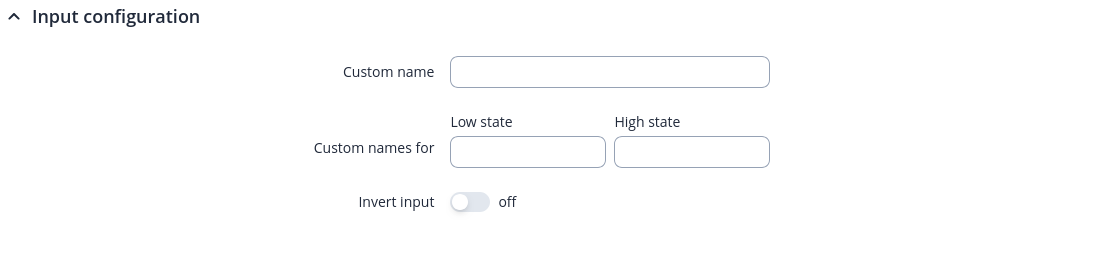
Input configuration
A Input configuration defines which `Inputs` will be used for impulse counting. Input configuration list is empty by default. Click the 'Add' button in order to create a new Input instance:
You will then be taken to the configuration page for the newly added input:
| Field | Value | Description |
|---|---|---|
| Enable | off | on; default: on | Enable input configuration. |
| Name | string; default: none | Name of input configuration. |
| GPIO pin | Input (3) ; default: Input (3) | Select GPIO pin for input configuration. |
| Edge | Rising | Falling | Both; default: Rising | Select the edge option to have the impulse counter increment on the signal`s transition from low to high, high to low, or both. |
| Debounce | integer; default: 0 | Debounce filters out rapid, unintended signals. Set between 0-1000 ms to ensure only stable inputs are registered. |
Statistics
Statistics page displays PIN statistics in routers local time.