Wiki mirrorView source
The information in this page is updated in accordance with firmware version RUTX_R_00.07.22.1.
Summary
The Serial Utilities page is used to make serial communication configurations of different types.
This manual page provides an overview of the Serial Utilities page in RUTX11 devices.
Modem Control
The Modem serial type is used to manage modem functionality which could be accessed using shell interface. For this purpose you may want use CR/LF (Carriage Return, Line Feed) capable applications like PuTTY on Windows and microcom, minicom, cutecom or similar applications on Linux.
Status
General settings
| Field | Value | Description |
|---|---|---|
| Enable | off | on; default: off | Turns the instance on or off. |
| Name | string; default: none | Instance name, generated by the user when first creating the configuration. |
| Device | USB RS232 interface; default: USB RS232 interface | Specifies which serial port will be used for serial communication. |
| Baud rate (USB) | integer [300..4000000]; default:9600 | Data rate for serial data transmission (in bits per second (bps)). |
| Data bits | 8; default: 8 | Number of data bits for each character. |
| Stop bits | 1 | 2; default: 1 | Stop bits sent at the end of every character allow the receiving signal hardware to detect the end of a character and to resynchronise with the character stream. Electronic devices usually use one stop bit. Two stop bits are required if slow electromechanical devices are used. |
| Parity | None | Odd | Even | Mark | Space; default: None | In serial transmission, parity is a method of detecting errors. An extra data bit is sent with each data character, arranged so that the number of 1 bits in each character, including the parity bit, is always odd or always even. If a byte is received with the wrong number of 1s, then it must have been corrupted. However, an even number of errors can pass the parity check.
|
| Flow control | None; default: None | In many circumstances a transmitter might be able to send data faster than the receiver is able to process it. To cope with this, serial lines often incorporate a "handshaking" method, usually distinguished between hardware and software handshaking. |
| Mode | Partial control | Full control; default: Partial control | Specifies modem control mode.
|
Advanced settings
| Field | Value | Description |
|---|---|---|
| Start up message | string; default: none | Prints message to serial device when modem control is ready. |
| Canonical mode | off | on; default: off | Forwards data to modem only when new line symbol ('\n') is detected. |
Console
Console mode requires no further configuration than the settings above and is used as a direct-access method to the device's shell interface. For this purpose you may want use such applications as PuTTY on Windows and microcom, minicom, picocom or similar applications on Linux.
Status
General settings
| Field | Value | Description |
|---|---|---|
| Enable | off | on; default: off | Turns the instance on or off. |
| Name | string; default: none | Instance name, generated by the user when first creating the configuration. |
| Device | USB RS232 interface; default: USB RS232 interface | Specifies which serial port will be used for serial communication. |
| Baud rate (USB) | integer [300..4000000]; default:9600 | Data rate for serial data transmission (in bits per second (bps)). |
| Data bits | 8; default: 8 | Number of data bits for each character. |
| Stop bits | 1 | 2; default: 1 | Stop bits sent at the end of every character allow the receiving signal hardware to detect the end of a character and to resynchronize with the character stream. Electronic devices usually use one stop bit. Two stop bits are required if slow electromechanical devices are used. |
| Parity | None | Odd | Even | Mark | Space; default: None | In serial transmission, parity is a method of detecting errors. An extra data bit is sent with each data character, arranged so that the number of 1 bits in each character, including the parity bit, is always odd or always even. If a byte is received with the wrong number of 1s, then it must have been corrupted. However, an even number of errors can pass the parity check.
|
| Flow control | None; default: None | In many circumstances a transmitter might be able to send data faster than the receiver is able to process it. To cope with this, serial lines often incorporate a "handshaking" method, usually distinguished between hardware and software handshaking. |
Over IP
The Over IP serial type is used to manage serial connections over a TCP/IP network.
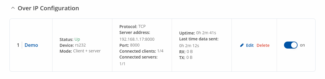
Instance Example
Here's an example demonstrating Over IP in action, running in Client + Server Mode.
Serial Device Configuration
Configure serial port communication parameters in the Serial Device Configuration section.
| Field | Value | Description |
|---|---|---|
| Enable | off | on; default: off | Turns the instance on or off. |
| Name | string; default: none | Instance name, generated by the user when first creating the configuration. |
| Device | USB RS232 interface; default: USB RS232 interface | Specifies which serial port will be used for serial communication. |
| Baud rate (USB) | integer [300..4000000]; default:9600 | Data rate for serial data transmission (in bits per second (bps)). |
| Data bits | 8; default: 8 | Number of data bits for each character. |
| Stop bits | 1 | 2; default: 1 | Stop bits sent at the end of every character allow the receiving signal hardware to detect the end of a character and to resynchronise with the character stream. Electronic devices usually use one stop bit. Two stop bits are required if slow electromechanical devices are used. |
| Parity | None | Odd | Even | Mark | Space; default: None | In serial transmission, parity is a method of detecting errors. An extra data bit is sent with each data character, arranged so that the number of 1 bits in each character, including the parity bit, is always odd or always even. If a byte is received with the wrong number of 1s, then it must have been corrupted. However, an even number of errors can pass the parity check.
|
| Flow control | None; default: None | In many circumstances a transmitter might be able to send data faster than the receiver is able to process it. To cope with this, serial lines often incorporate a "handshaking" method, usually distinguished between hardware and software handshaking. |
Over IP Configuration Settings
You can configure network related parameters of the serial connection in the Over IP Configuration secion.
| Field | Value | Description |
|---|---|---|
| Mode | Server | Client | Client + server | Bidirect; default: Server | This device's role in the connection:
|
| Protocol | TCP | UDP; default: TCP | Protocol used in the communication process. |
| Client: Destination address | IP | Port; default: empty | Specify server address and port for client to connect to. E.g first field for address second for port. 16 destination addresses are allowed. |
| Server: UDP: Predefined addresses | IP | Port; default: empty | Set predefined IP and port for UDP connection. E.g first field for address second for port. |
| Listening port | [1..65535]; default: empty | When enabled, all data will be transmitted transparently. |
| Field | Value | Description |
|---|---|---|
| Use TLS/SSL | off | on; default: off | Mark to use TLS/SSL for connection. |
| TLS version | Support all | tlsv1.0 | tlsv1.1 | tlsv1.2 | tlsv1.3; default: Support all | Minimum TLS version allowed to be used. |
| TLS type | Certificate based | Pre-Shared-Key based; default: Certificate based | Select the type of TLS encryption. |
| Require certificate | off | on; default: on | Demand certificate and key from peer and verify them against certificate authority. |
| Verify host | off | on; default: off | Check if the server certificates Common Name (CN) matches hostname to which client is connecting. |
| Certificate files from device | off | on; default: off | Choose this option if you want to select certificate files from device. Certificate files can be generated <a class=link href="/system/admin/certificates/generation">here</a>. |
| Certificate file | .crt file; default: none | Upload certificate file. |
| Key file | .key file; default: none | Upload key file. |
| CA file | .ca file; default: none | Upload CA file. |
| Pre-Shared-Key | string; default: none | The pre-shared-key in hex format with no leading “0x”. |
| Identify | string; default: none | Specify the identity. |
| Field | Value | Description |
|---|---|---|
| Raw mode | off | on; default: on | When enabled, all data will be transmitted transparently. |
| Remove all zeros | off | on; default: off | When checked, indicates that the first hex zeros should be skipped. |
| Inactivity timeout | integer [0..36000]; default: 300 | Specifies period of time in seconds, where server connection must be inactive, to disconnect client. To disable timeout input 0. |
| Serial timeout | integer [0..1000]; default: none | Specifies the maximum milliseconds to wait for serial data. |
| Max clients | integer [1..32]; default: 4 | Specify how many clients are allowed to connect simultaneously. |
| TCP echo | on | off; default: off | Enable software TCP echo. |
| Close connections | on | off; default: off | Close TCP connections everytime data is sent or received (might result in serial data loss). |
| Keep alive | on | off; default: off | Enable keep alive. |
| Keep alive time | integer [0..32000]; default: 0 | Close TCP connections everytime data is sent or received (might result in serial data loss). |
| Keep alive interval | integer [0..32000]; default: 0 | The interval between subsequential keepalive probes. |
| Keep alive probes | integer [0..32000]; default: 0 | The number of unacknowledged probes. |
IP Filter
The IP Filter section is used for configuring which network is allowed to communicate with the device. You may add a new instance by selecting the Interface and pressing Add.
Then enter the IP address and save.