Wiki mirrorView source
This Wiki page contains the online version of the Quick Start Guide (QSG) for the TSW200 Switch. Here you will find an overview of the various components found on the front and back sides of a TSW200 switch, basic hardware installation, device specifications and general safety information. It is highly recommended that you acquaint yourself with with the Quick Start Guide before using the device. If you own a TSW200 switch, you can also find a printed version of the Quick Start Guide in the device's package.
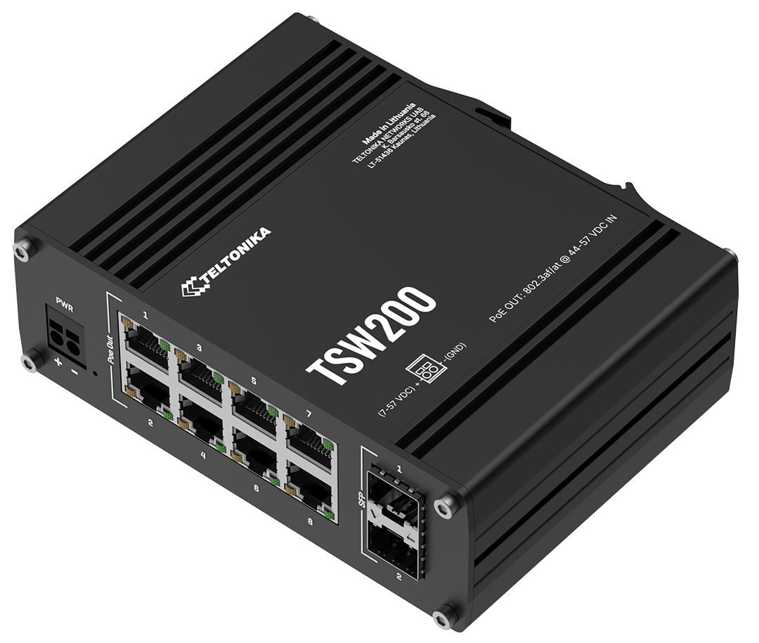 | 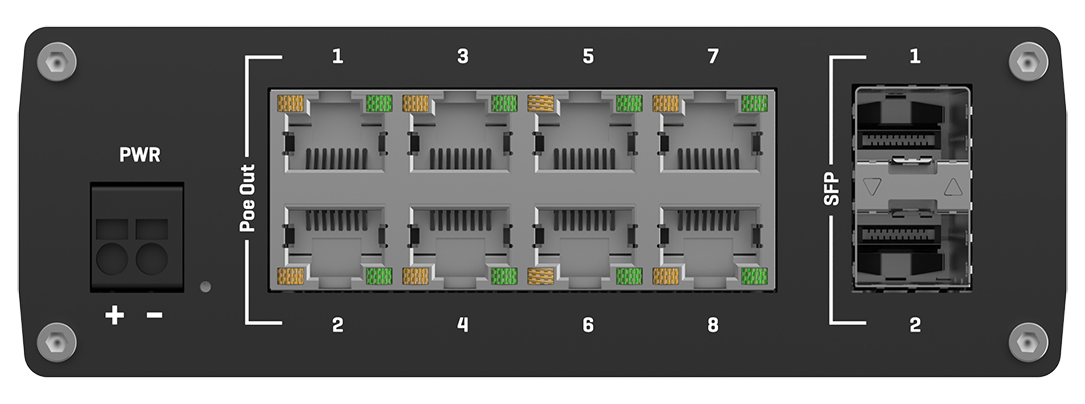 |  |
Front view
| No. | Description | |
|---|---|---|
| 1 | 2 pin power socket | |
| 2 | Power LED | |
| 3 | LAN LEDs | |
| 4 | PoE powered Ethernet ports | |
| 5 | SFP port | |
| 6 | SFP LEDs | |
Back view
| No. | Description | |
|---|---|---|
| 1 | Grounding screw | |
Connectors
2 pin power socket
| No. | Description | Wire color | |
|---|---|---|---|
| 1 | Power | Red | |
| 2 | Ground | Black | |
Ethernet port
| No. | Action | Describtion | |
|---|---|---|---|
| 1 | Orange LED lit | 10/100 Mbps link established | |
| 2 | Orange LED blinking | Active link connection | |
| 3 | Green LED lit | 1000 Mbps link established | |
SFP port
| No. | Action | Describtion | |
|---|---|---|---|
| 1 | Down LED lit | Lower port link established | |
| 2 | Down LED blinking | Lower port active traffic | |
| 3 | Up LED lit | Upper port link established | |
| 4 | Up LED blinking | Upper port active traffic | |
Safety information
TSW200 switch must be used in compliance with any and all applicable national and international laws and with any special restrictions regulating the utilization of the communication module in prescribed applications and environments.
| Technical specifications | |
|---|---|
| Input voltage range* | 7 - 57 V |
| Max power consumption | 5.5 W |
| Max PoE power budget at PSE | 240 W |
| Max Ethernet cable length | 100 m |
* PoE operates properly only when connected power supply outputs 44 V or higher voltage.
PoE standards
This device uses PoE alternative B.
- PoE Alternative A for TSW200 was introduced in Batch 42; earlier batches used PoE Alternative B
The difference between PoE alternative A and alternative B
Alternative A:
802.3af and 802.3at Alternative A connection. The power sourcing equipment applies a positive voltage to pins 1-2 and a negative voltage to pins 3-6.
| Pins at switch | T568A Color | T568B Color | 10/100 Alternative A, mixed DC & data | 1000 (1 gigabit) Alternative A, DC & bi-data | ||
| Pin 1 | white/green stripe | white/orange stripe | Rx + | DC + | TxRx A + | DC + |
| Pin 2 | green solid | orange solid | Rx − | DC + | TxRx A − | DC + |
| Pin 3 | white/orange stripe | white/green stripe | Tx + | DC − | TxRx B + | DC − |
| Pin 4 | blue solid | blue solid | Unused | Unused | TxRx C + | |
| Pin 5 | white/blue stripe | white/blue stripe | Unused | Unused | TxRx C - | |
| Pin 6 | orange solid | green solid | Tx − | DC − | TxRx B − | DC − |
| Pin 7 | white/brown stripe | white/brown stripe | Unused | Unused | TxRx D + | |
| Pin 8 | brown solid | brown solid | Unused | Unused | TxRx D - |
Alternative B:
802.3af and 802.3at Alternative B connection. The power sourcing equipment applies a positive voltage to pins 4-5 and a negative voltage to pins 7-8.
| Pins at switch | T568A Color | T568B Color | 10/100 Alternative B, DC on spares | 1000 (1 gigabit) Alternative B, DC & bi-data | ||
| Pin 1 | white/green stripe | white/orange stripe | Rx + | TxRx A + | ||
| Pin 2 | green solid | orange solid | Rx − | TxRx A − | ||
| Pin 3 | white/orange stripe | white/green stripe | Tx + | TxRx B + | ||
| Pin 4 | blue solid | blue solid | DC + | TxRx C + | DC + | |
| Pin 5 | white/blue stripe | white/blue stripe | DC + | TxRx C - | DC + | |
| Pin 6 | orange solid | green solid | Tx − | TxRx B − | ||
| Pin 7 | white/brown stripe | white/brown stripe | DC − | TxRx D + | DC − | |
| Pin 8 | brown solid | brown solid | DC − | TxRx D - | DC − |
日本国内専用です
本製品を電気通信事業者(移動体通信事業者、固定通信事業者、インターネットプロバイダなど)の電気通信回線(または公衆無線LAN)に直接接続することはできません。電気通信事業者の公衆電気通信回線設備に接続する場合は、必ず日本の「電気通信事業法」で認められた機器(ルーター、ゲートウェイ、モデムなど)を介して接続してください。
 This sign on the package means that all used electronic and electric equipment should not be mixed with general household waste
BSMI-RoHS table
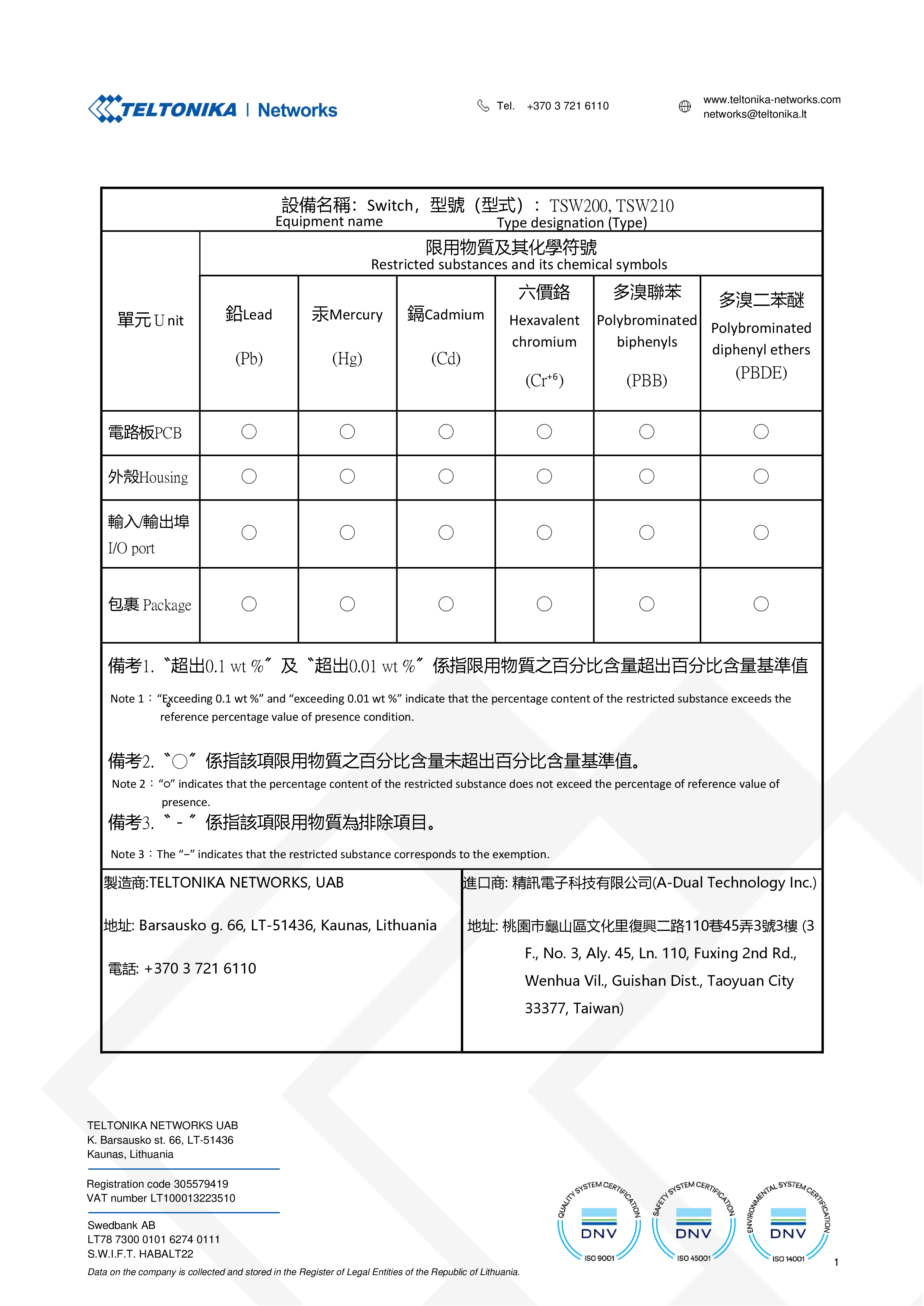 |
To download a PDF version of the TSW200 BSMI RoHS table, click here.